Fixed circuit warehouse equipment or machines (normally automated) used in an installation are those that always follow the same route on a pre-established circuit. This category of devices includes conveyors, electrified monorail systems, automated guided vehicles (AGV and LGV), and, of course, stacker cranes.
Other vehicles commonly used in a warehouse, such as all types of forklifts, cannot be included in this group. Despite operating along routes inside the warehouse that are more or less preestablished, guided and wire-guided turret trucks do not belong to this group either, since they can move freely around the warehouse without restriction if so desired.
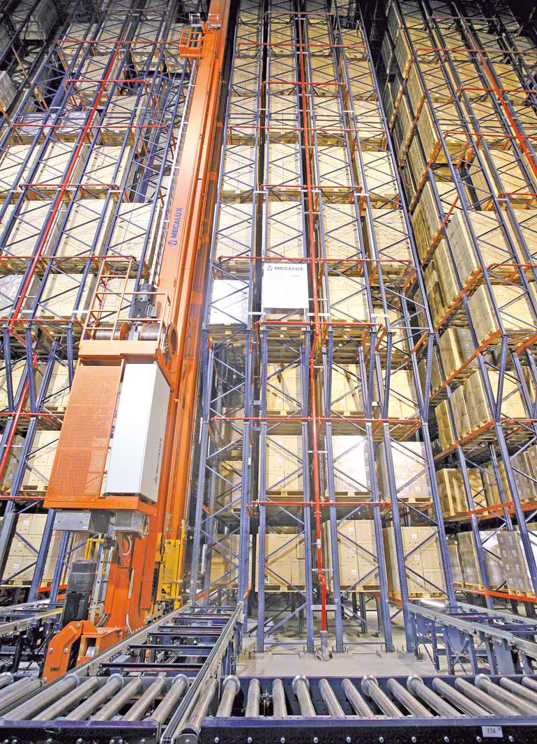
Clad-rack warehouse for the pharmaceutical sector.
Fixed-route devices are ideal for use within a clad-rack warehouse. However, it is important to establish how to use them and in what way. This issue is addressed below.
Precision positioning
The different systems within this group have elements that guarantee that they are correctly positioned inside the facility or among the racking units at all times. Stacker cranes, for example, have laser rangefinders, electronic stopping systems, devices for dynamic detection, for accurate positioning, etc.
These devices act as the eyes and ears of the automated systems, so that the devices used are perfectly positioned at all times and can handle loads without bumping into, or bumping the goods into, the racking units. They can also, for example, detect whether a space is already occupied or whether there are obstacles impeding their movement. These positioning systems are essential in the safe construction of very high clad-rack warehouses.
Supports for fixed-route elements
Supports for the fixed-route devices are designed on the basis of the specific characteristics of each. Roller conveyors are supported on stands attached to the floor. Stacker cranes are supported on two rails, with one attached to the floor and the other attached to the upper bracing of the racking units.
Supports for roller conveyors
As explained in the "Handling Equipment" section, roller conveyors are adapted to the features of the working cycle and the fixed route that must be taken by the goods being moved. To this end, they consist mainly of straight stretches, which can be split into branches using various types of standardised switches.
There is also the option to connect conveyors on different height levels by using lifts.
These devices are manufactured in standard sections varying in length between 1.5 and 3 metres. Depending on the characteristics of the floor and the weight of the section and load, at least one support stand is fitted to each end of a section. These stands are bolted into the ground using adjustable bearing plates.
At times, conveyors are located at points where loads from different sources within the warehouse come together, so special fixing to the floor may be required depending on the total weight of the group of transport elements and loads.
Supports for stacker cranes
Due to their height, stacker cranes require more support than conveyors. They use two rails, with one fixed to the floor and another fixed to the upper bracing of the racking unit’s aisles.
The lower rail must be extremely strong, given that a machine of this type can transmit loads in excess of 18 tonnes onto each wheel.
The lower rails used are at least 152 mm high and have welded footings of 250 x 150 mm installed along the rail every +-460 mm. These footings are fixed to the ground using four screws (two fixed and another two for levelling), which come with a nut and locknut and have a pathway below ground level of around 152 mm.
For large-scale stacker cranes, which are commonly used in self-supporting warehouses, on the other hand, the upper rail is fixed to the highest bracings of the racking units, since there is no other structure above these (even the roof is attached to the racking units).
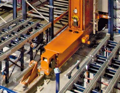 |
| Detail of a lower support or frame for a stacker crane and of a rail. |
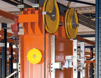 |
| Upper support for a stacker crane and upper rail. |
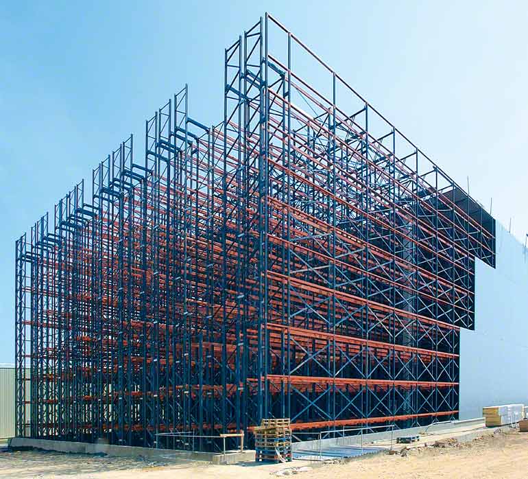 |
| In clad-rack installations, the racks form the structure of the building itself. |
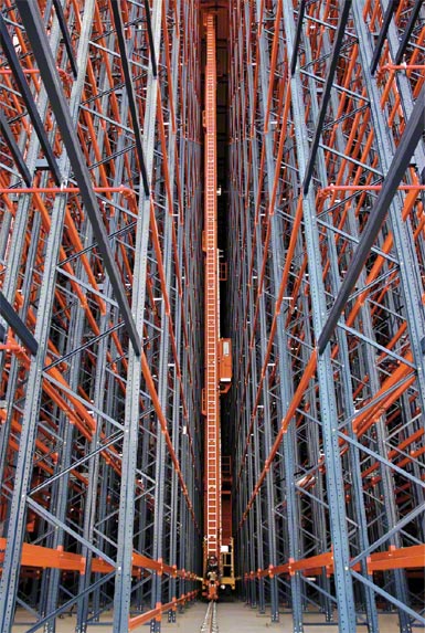 |
| Stacker crane inside a clad-rack warehouse structure. |
Clearances for fixed-route devices
In self-supporting warehouses margins are very tight (practically a fraction of a centimetre). Therefore, it is very important to specify the minimum clearances that must be observed by the designer.
For design purposes, the critical points that require maximum attention in terms of clearances are the working aisles, the load levels, and the longitudinal positioning of the loads.
Clearances in working aisles
The required width of a working aisle in a clad-rack warehouse is determined by the circulation space required by a stacker crane moving through the aisle and the width of the loads that will be transported.
Given that these machines are guided at both the top and the bottom, the chance of deviation from the route is almost zero. There is only a calculated risk of buckling, caused by the great height of these devices. In general, this buckling has been foreseen by the manufacturer, who will have implemented the necessary measures to prevent this.
Positioning of loads on racking units
The greatest problem in a warehouse is normally due to the potential for the loads to fall. Some goods may protrude from the racking units, and take up more space than planned.
This type of problem can be avoided by correctly establishing the characteristics of the units that will be stored in the facility, before it is designed, and strictly complying with the standards for safety and the use of devices once the facility is operational. Determining clearances for the positioning of loads is an issue of vital importance at this stage.
Clearances are the distances that must be left between unit loads and elements of the racking unit. They are expressed in relation to the total size of the units, including any overhang that may exist.
Depending on the weight of the goods and the height of the warehouse planned, two or three units may be placed lengthwise in each compartment.
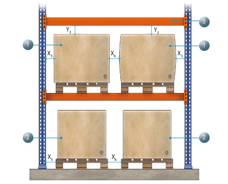
In the layouts that accompany this text, the clearances are represented, in the bay as well as in the depth, for the case of two pallets per bay. The keys to the measurements represented by the letters (X1, X2...) are defined in the tables below. The minimum clearances that must be respected are defined in Standard EN 15620 and are applied depending on the type of shelving (class 100, 200, AS/RS stacker cranes, or class 300, turret trucks, or class 400, retractable and counterbalanced forklifts).
|
||||||||||||||||||||||||||||||||||||||||||||||||||||||||||||||||||||||||||||||||||||||||||||||||||||||||||||

